Second Cut
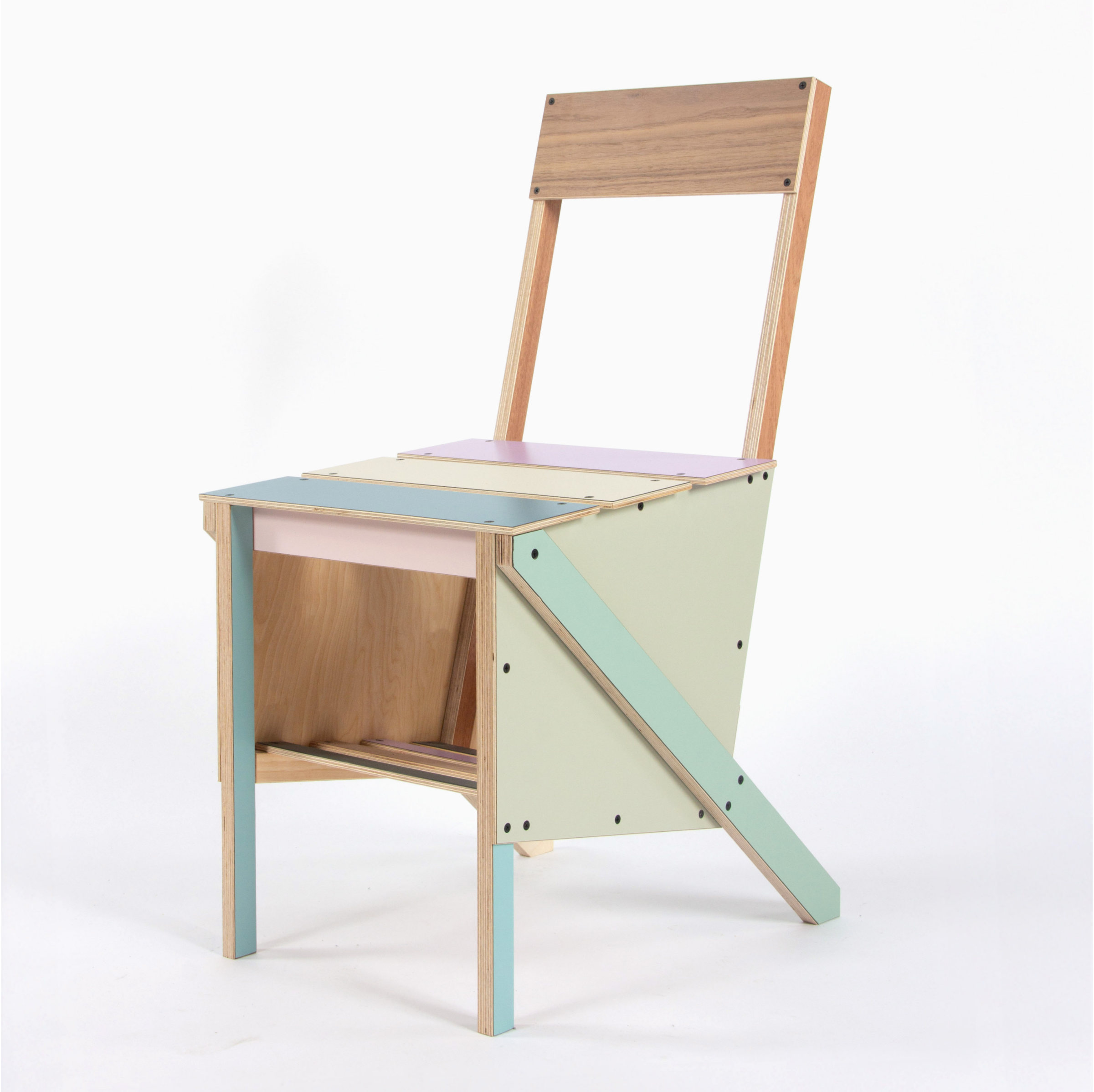
A structural exploration of plywood joinery, built from Sons of Beasley laminated ply offcuts from bespoke kitchen company Plykea.
- Problem
- Turn a fixed stock of laminated ply offcuts into a chair, letting the sizes and colours of the material set the rules.
- Approach
- Tested joints small in MDF, refined them through 1:5 models, then planned every screw and step of assembly in CAD before a 1:1 prototype.
- Outcome
- A colourful working chair with a 4° forward seat angle and storage beneath the seat.
- Role
- Designer & maker
- Timeline
- Studio project
- Team
- Solo
- Tools
- CAD, Mitre saw, Drill driver, Clamps
Skills
- Structural joinery
- Scale modelling
- Assembly planning
- Technical drawing
- Woodwork
Phases
- 01Research
- 02Model
- 03Plan
- 04Prototype
- 05Make
01 / Research
Finding structure at a small scale first.
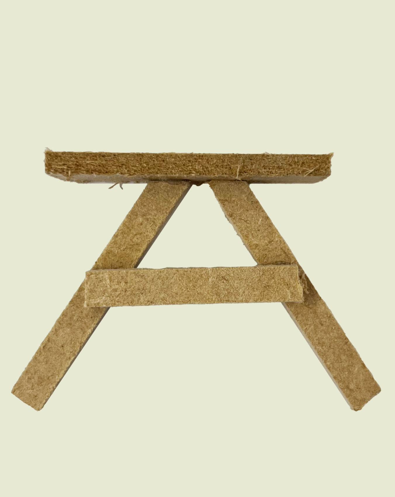
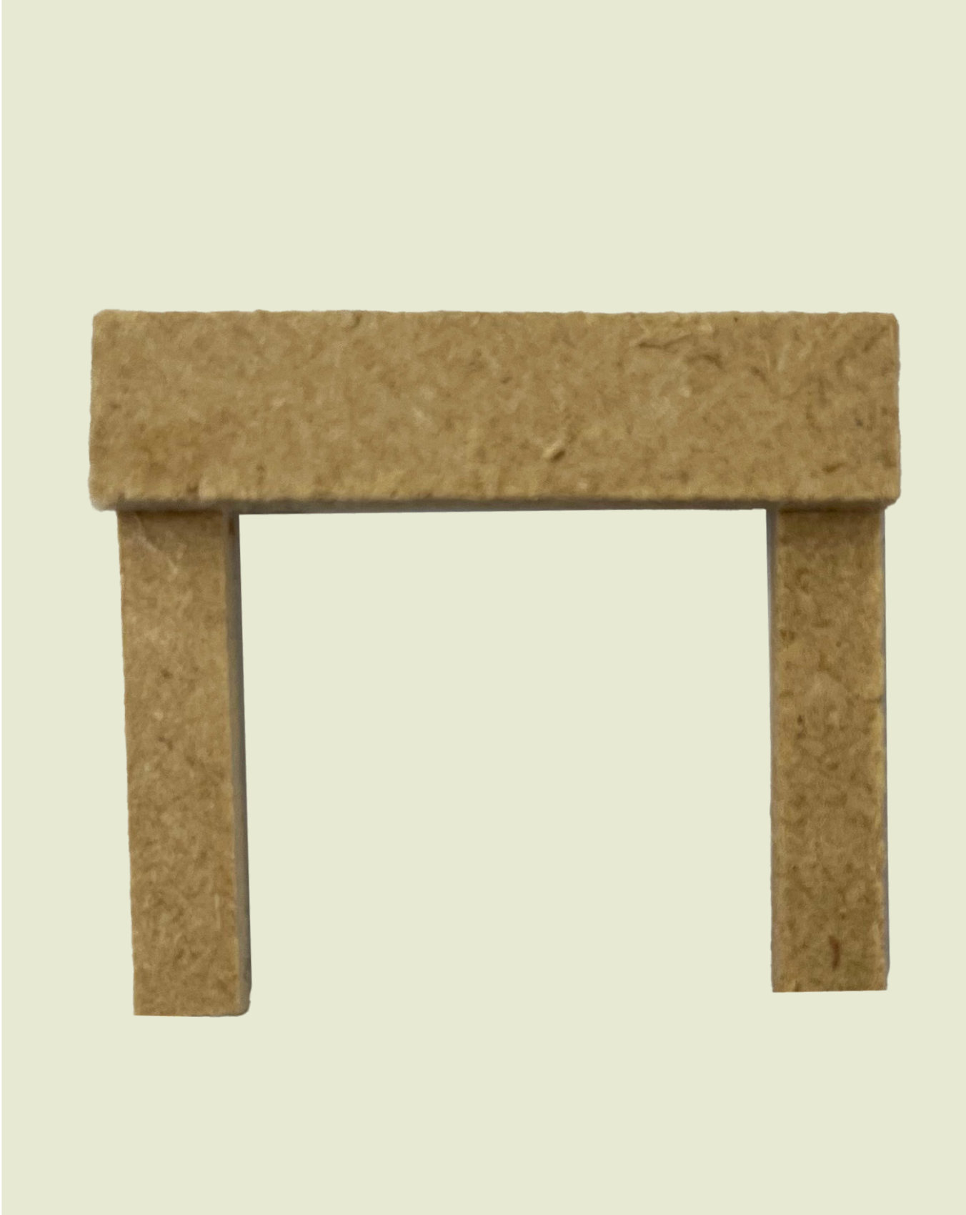
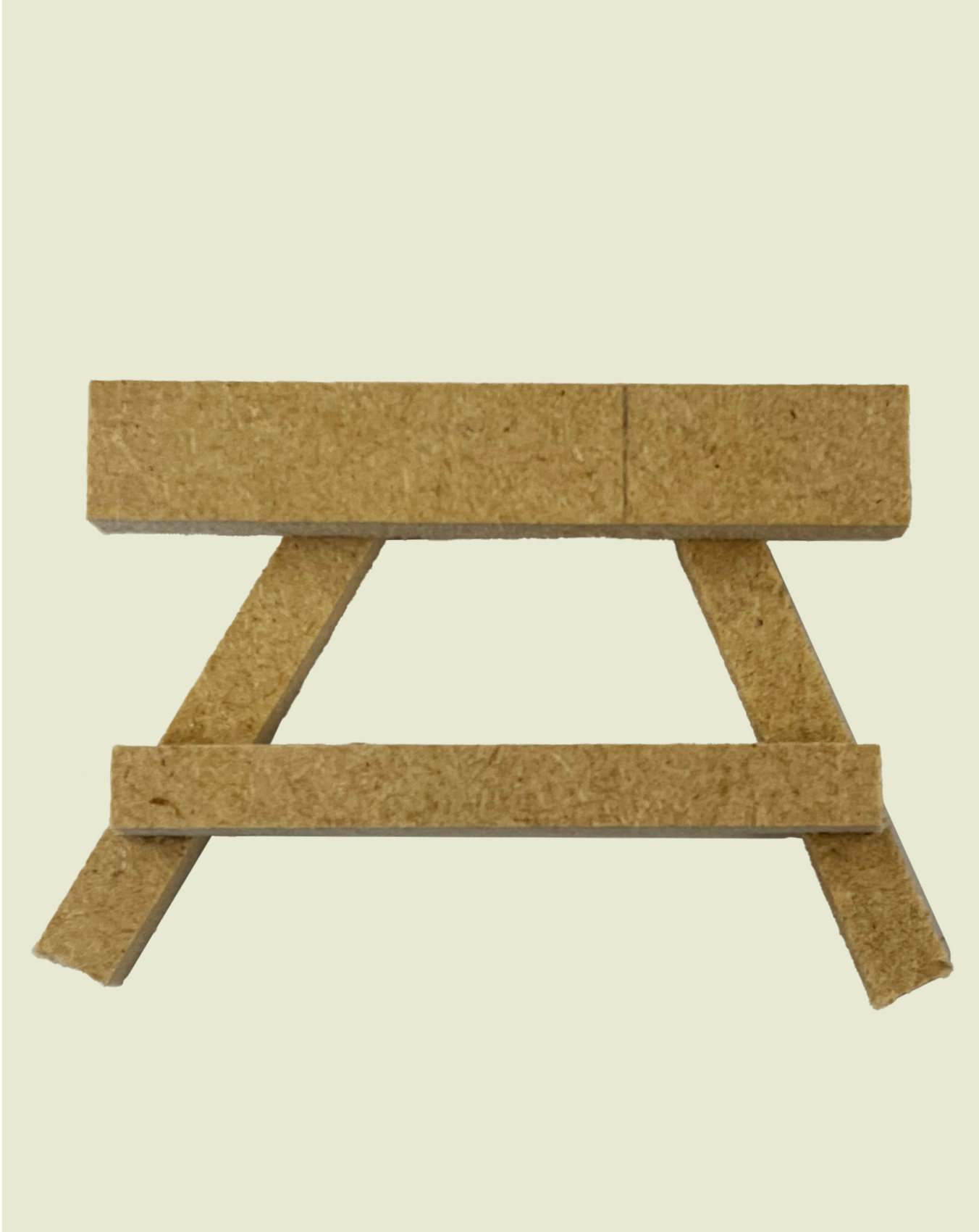
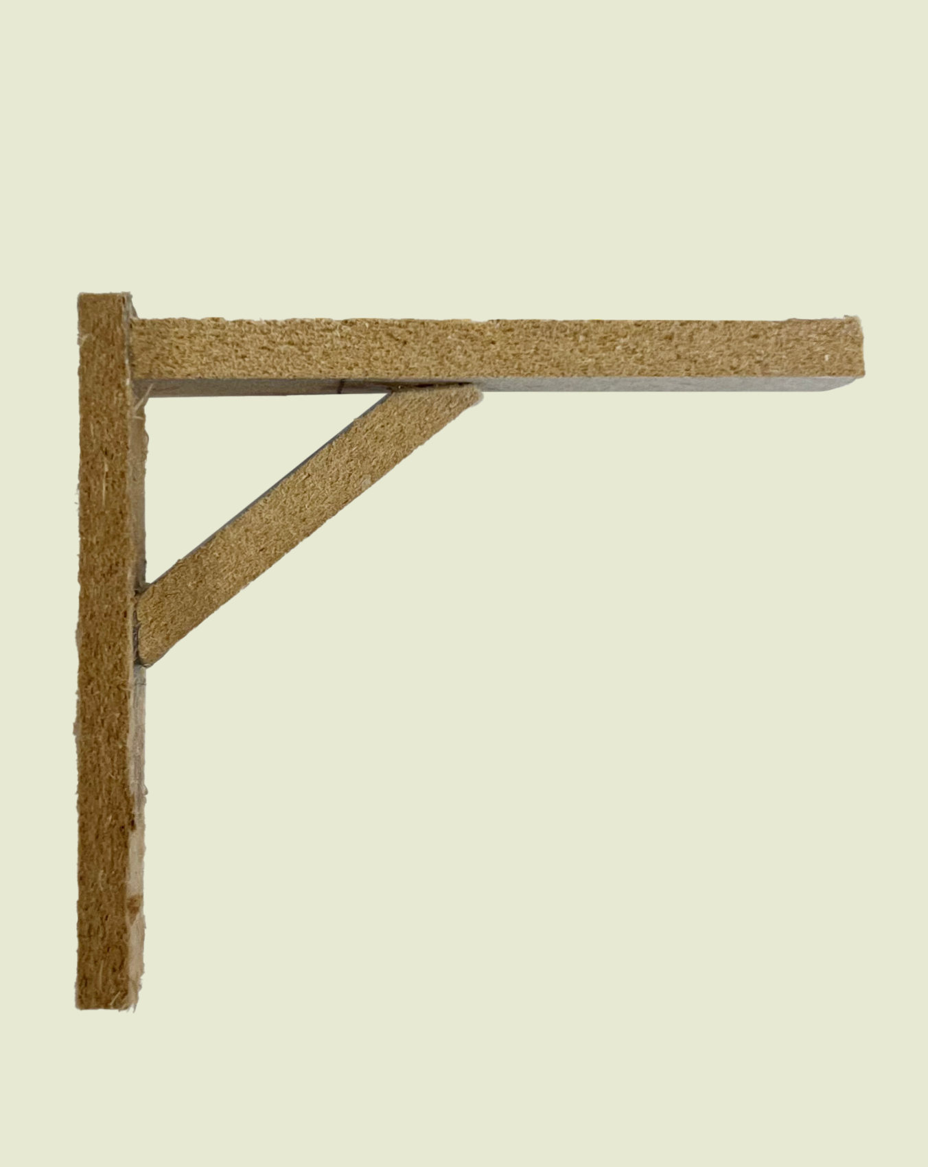
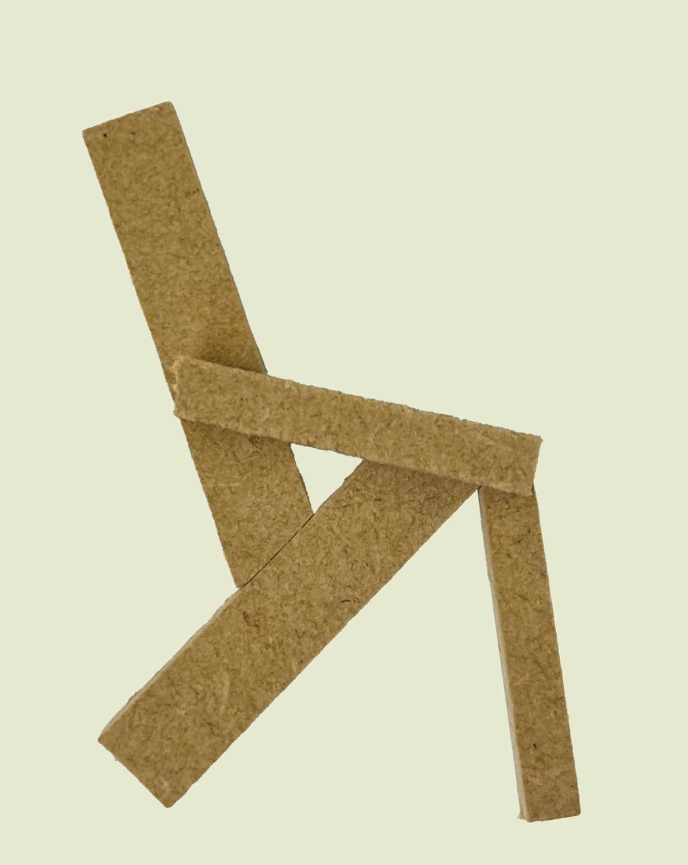
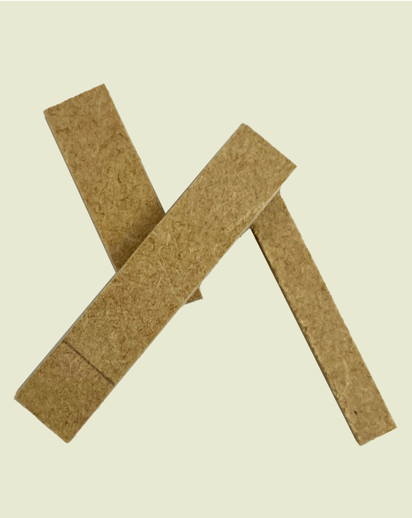
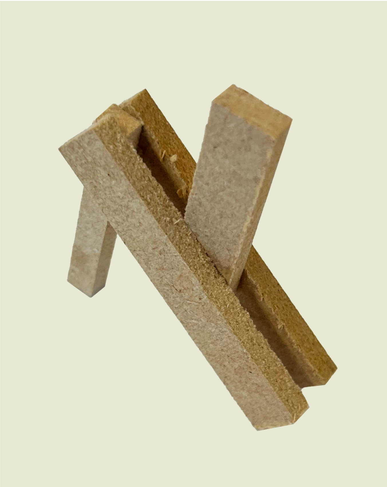
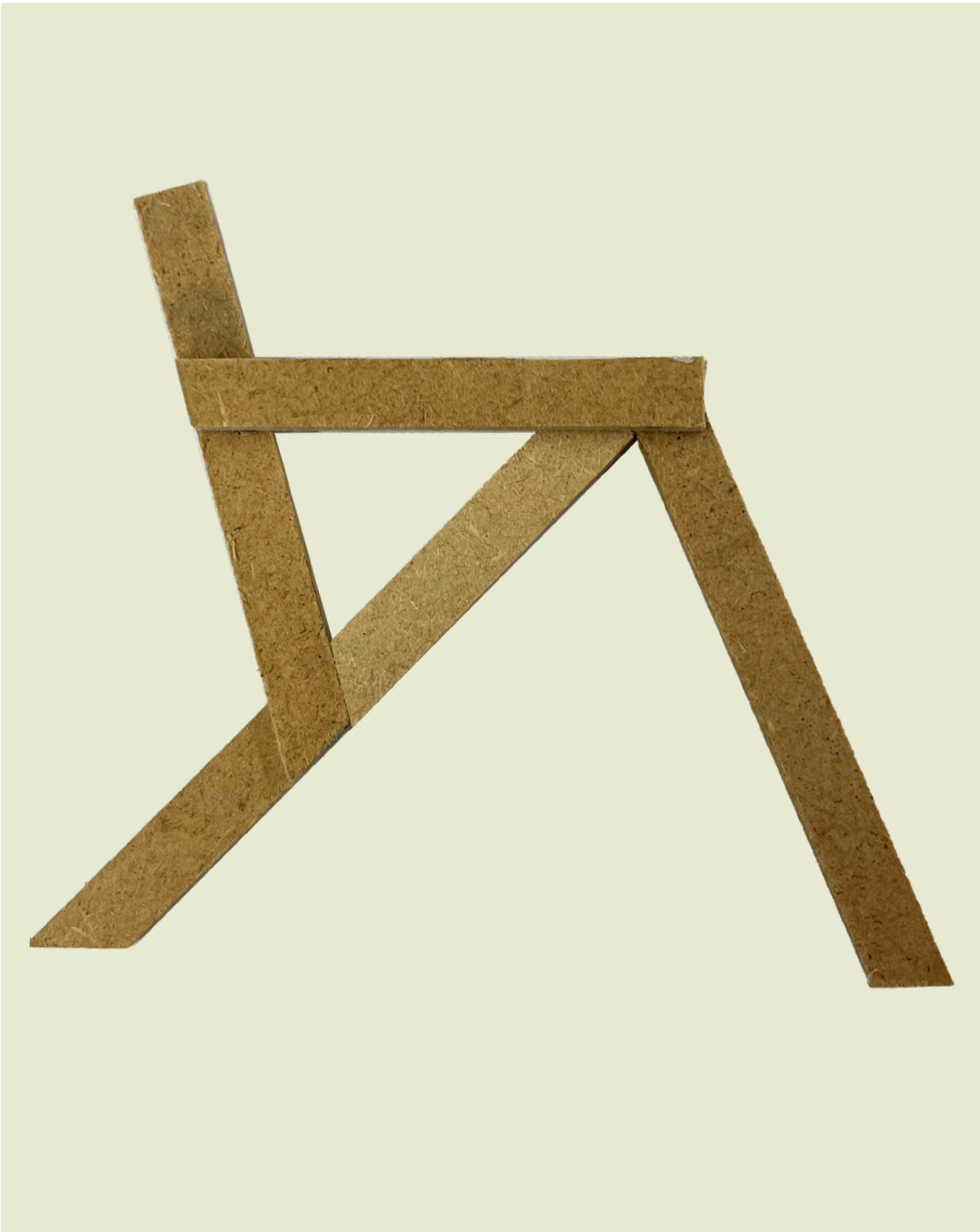
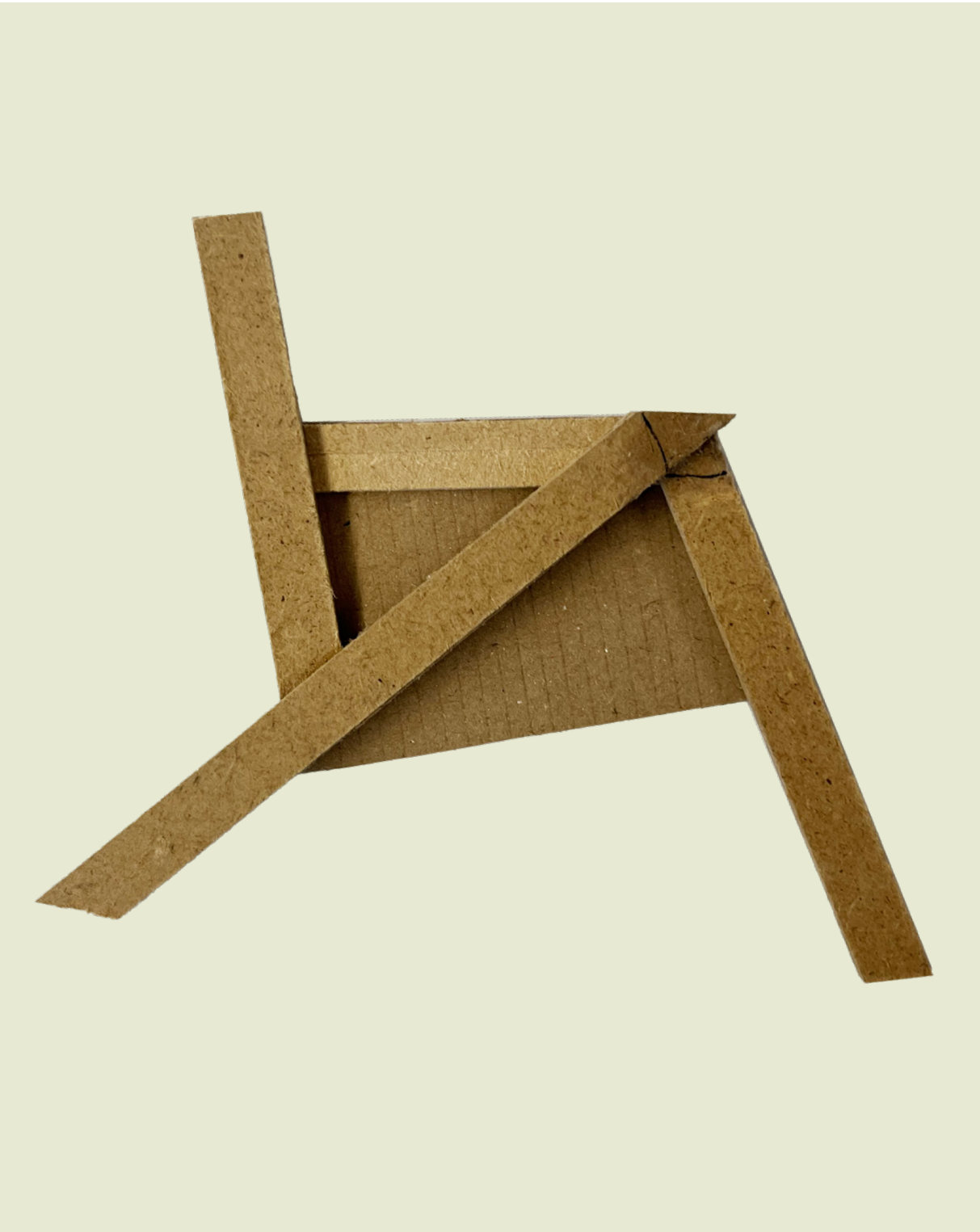
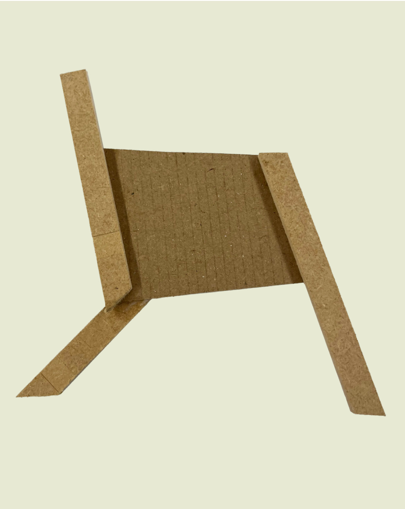
I experimented with structural joinery in MDF at small scale, then developed each idea based on where it was strong and where it failed.
02 / Development
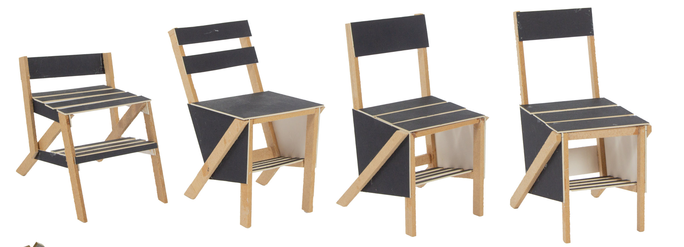
Four chairs at 1:5, one joinery principle.
The strongest test, a crossed brace, became the guiding principle. Scale models explored how it could carry a seat, a backrest and a storage shelf.
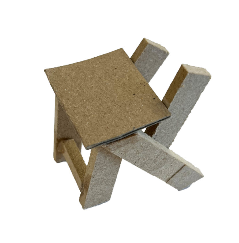
Guiding principle
1:5 scale model development using the joinery tests.
03 / Planning
Every screw placed before a single cut.
In CAD I planned screw placement and the order of assembly, panel by panel. The chair is held together by 62 screws in five lengths.
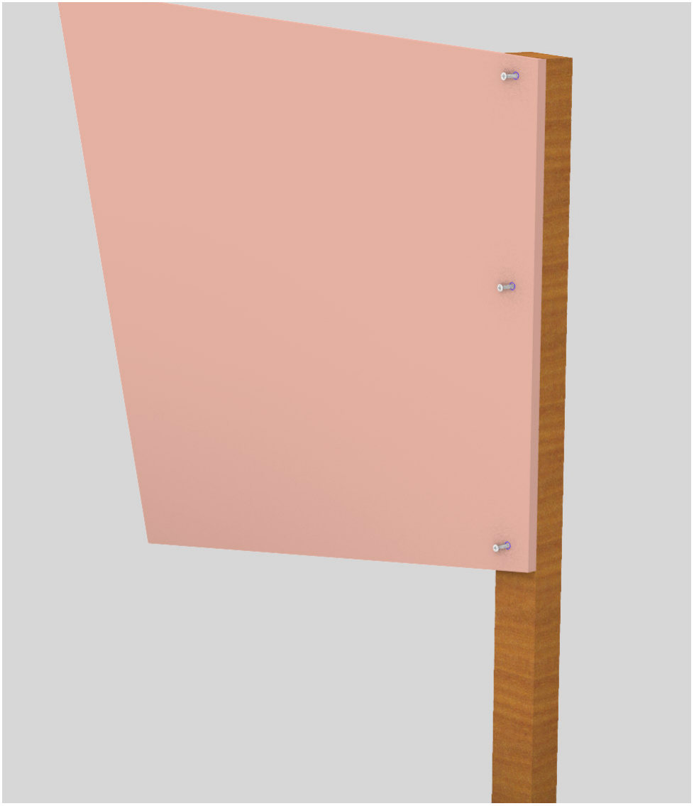
012 sides × (3 × 20 mm)
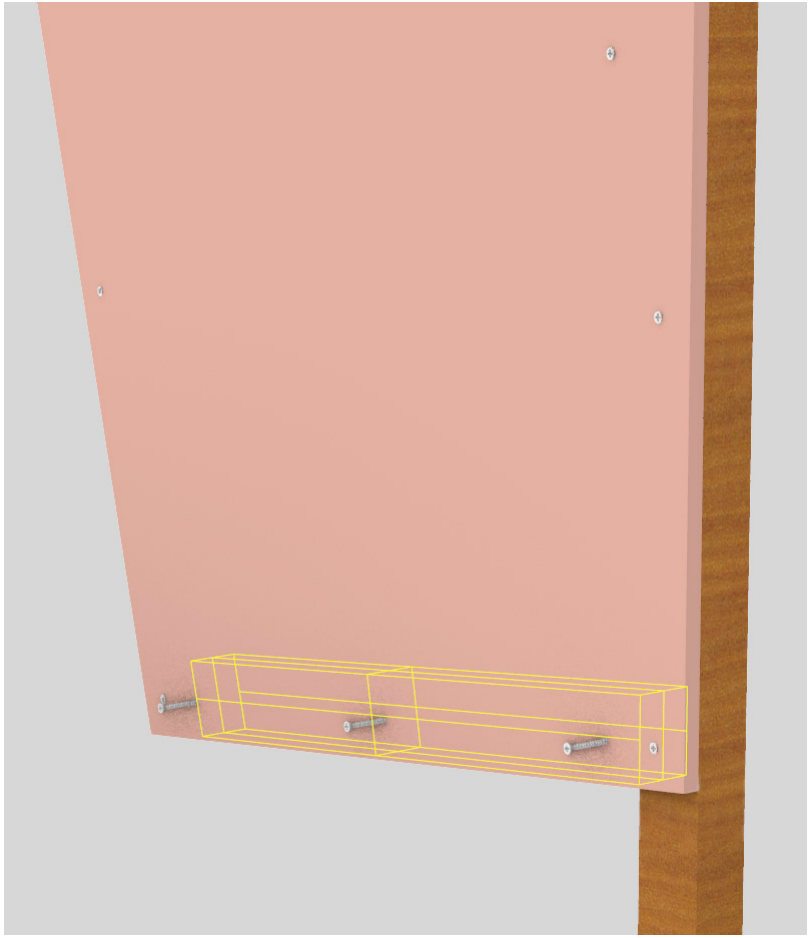
022 sides × (3 × 20 mm)
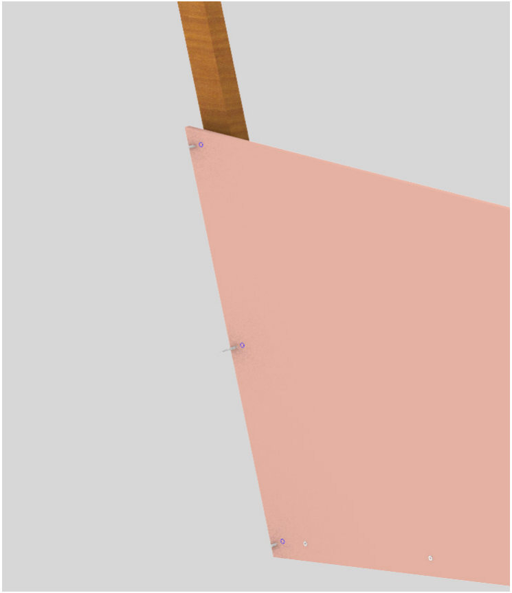
032 sides × (3 × 20 mm)
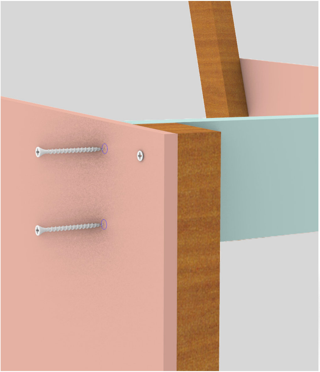
042 sides × (2 × 30 mm)
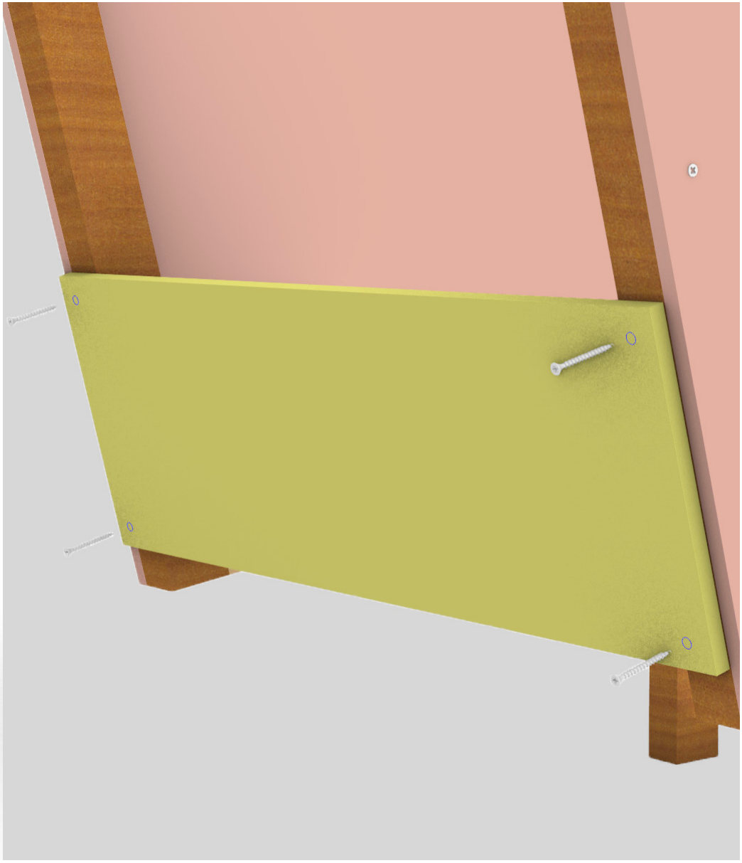
054 × 25 mm
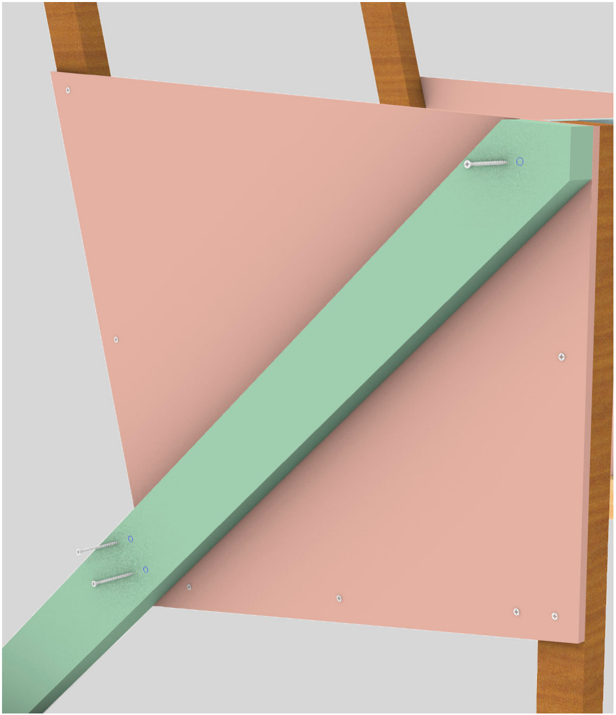
062 sides × (3 × 35 mm)
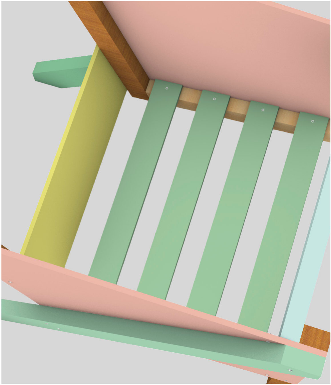
074 panels × (2 × 25 mm)
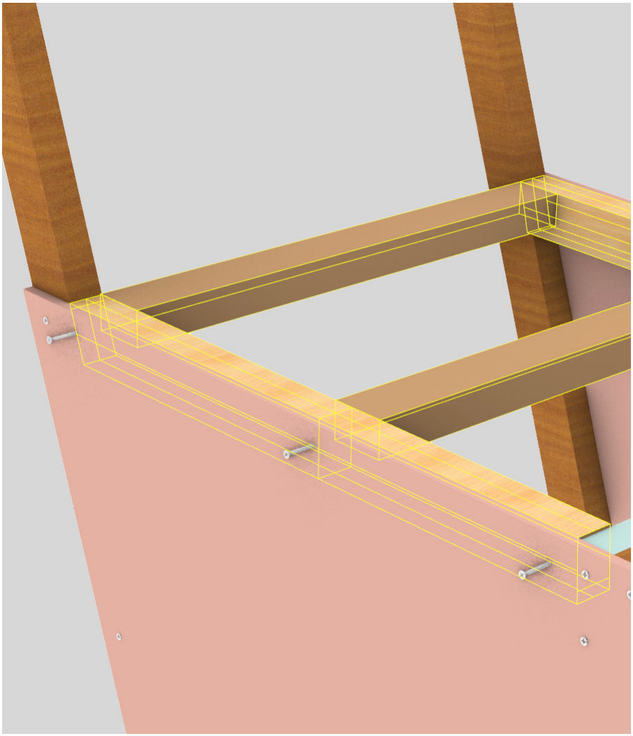
082 sides × (2 × 40 mm) + 2 sides × (1 × 20 mm)
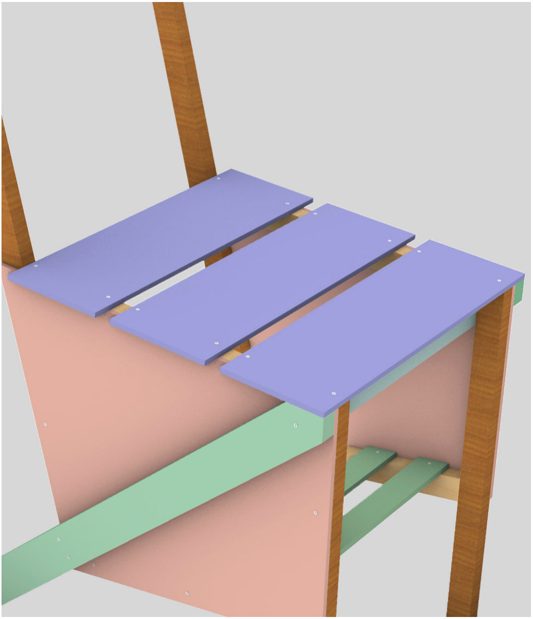
093 panels × (4 × 25 mm)
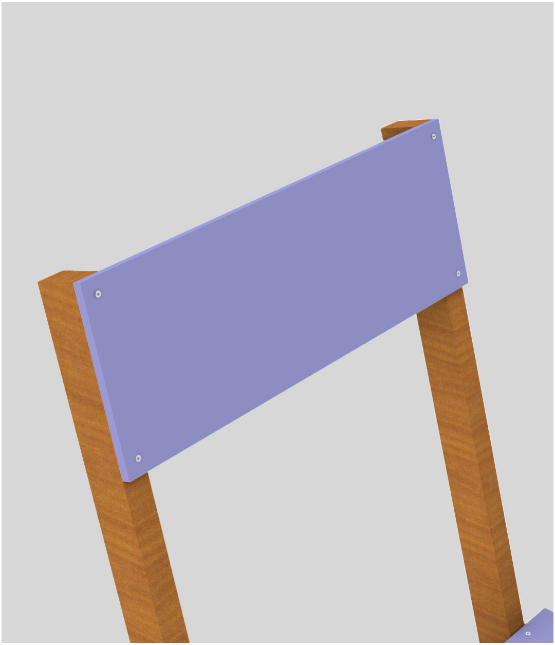
104 × 25 mm
Total 3.5 mm screws: 20 × 20 mm, 28 × 25 mm, 4 × 30 mm, 6 × 35 mm, 4 × 40 mm.
04 / Technical
Twelve parts, cut from 6 mm and 20 mm ply.
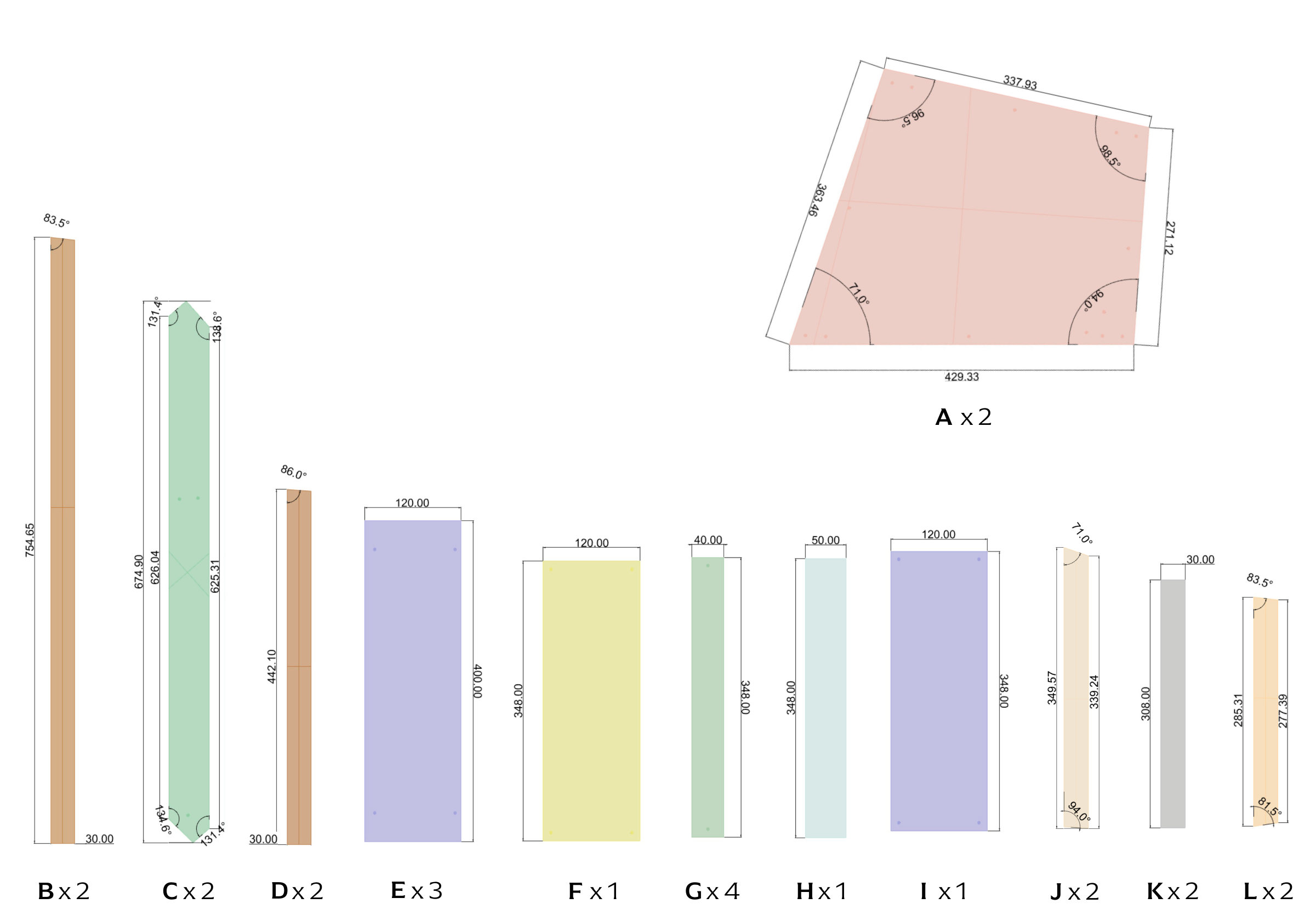
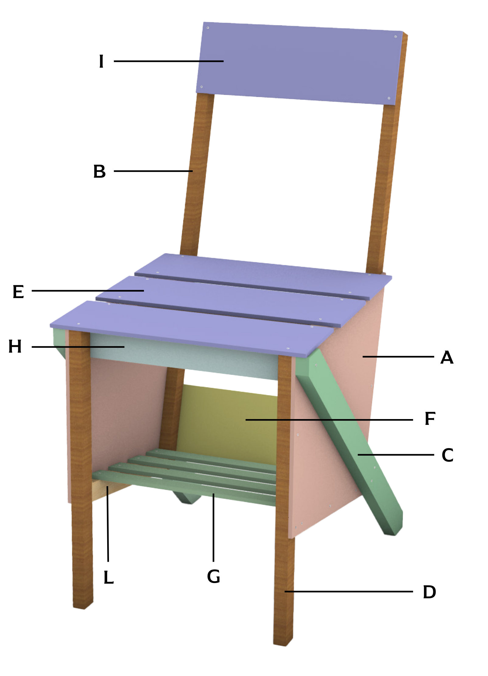
Cutting list for the final chair, keyed to the labelled model.
- Unique parts, A to L
- 12
- Unique parts, A to L
- Ply thicknesses
- 6 & 20 mm
- Ply thicknesses
- 3.5 mm screws
- 62
- 3.5 mm screws
05 / Making
From a 1:1 prototype to the final chair.
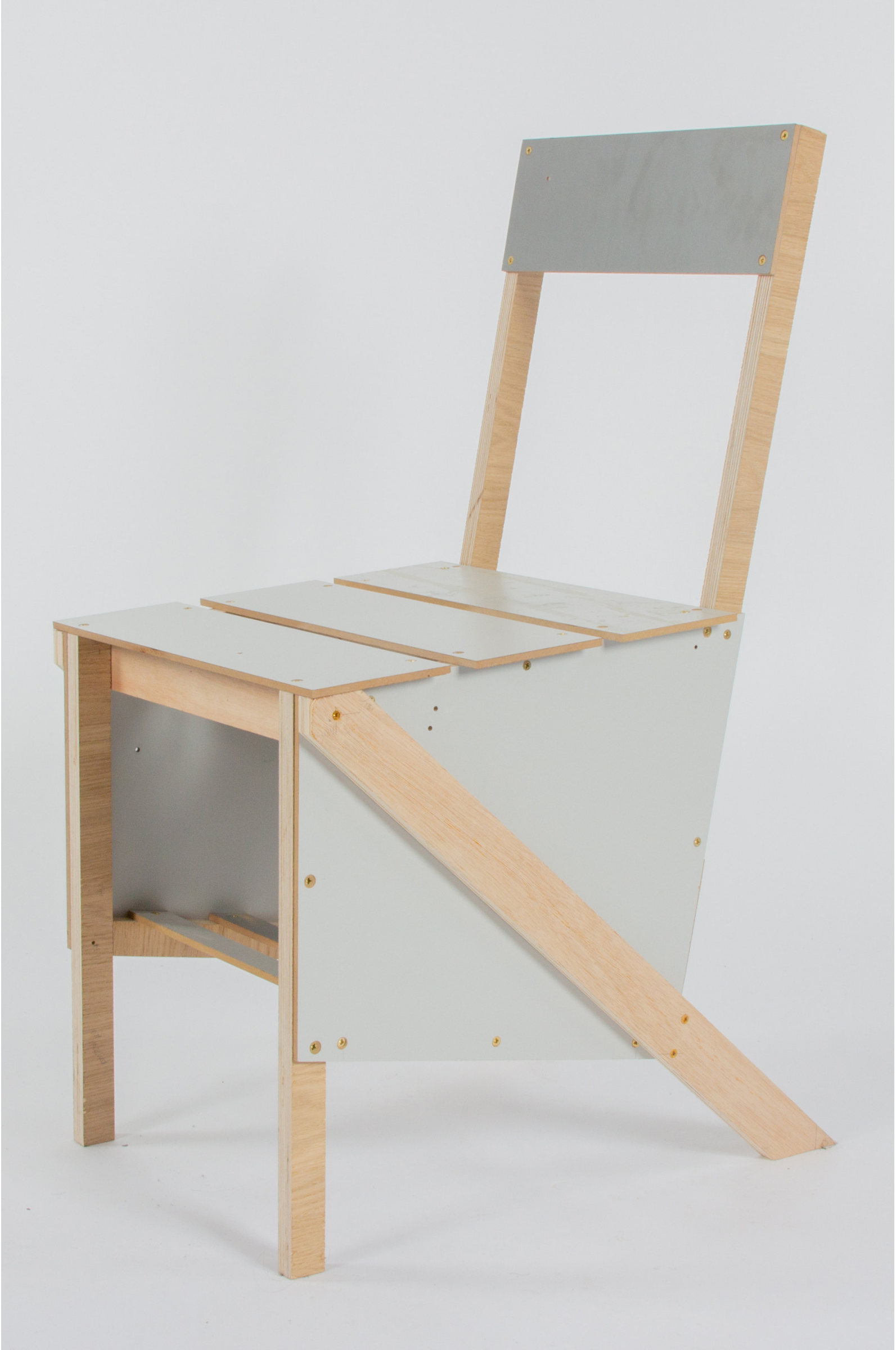
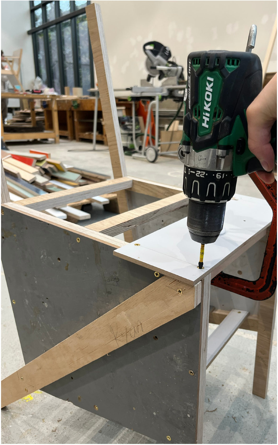
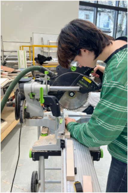
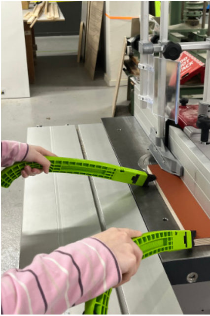
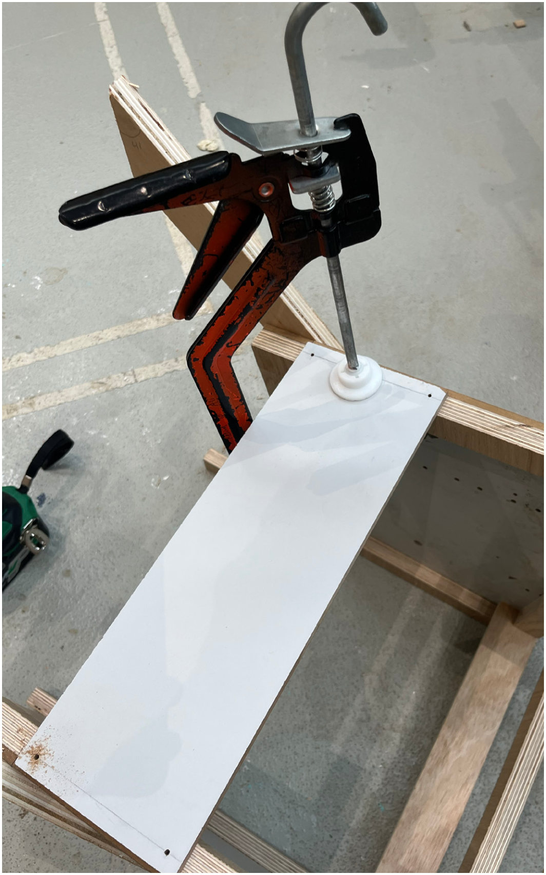
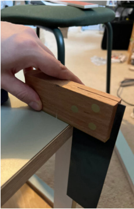
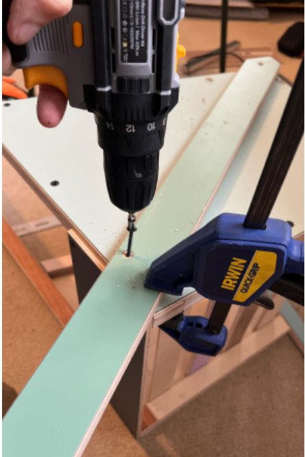
Cutting, spindling, marking, aligning, clamping, drilling, countersinking, screwing. The prototype led to accurate screw placements that prevent crossover, a planned assembly order and a more comfortable backrest angle.
06 / Outcome
A chair for working, with room underneath.
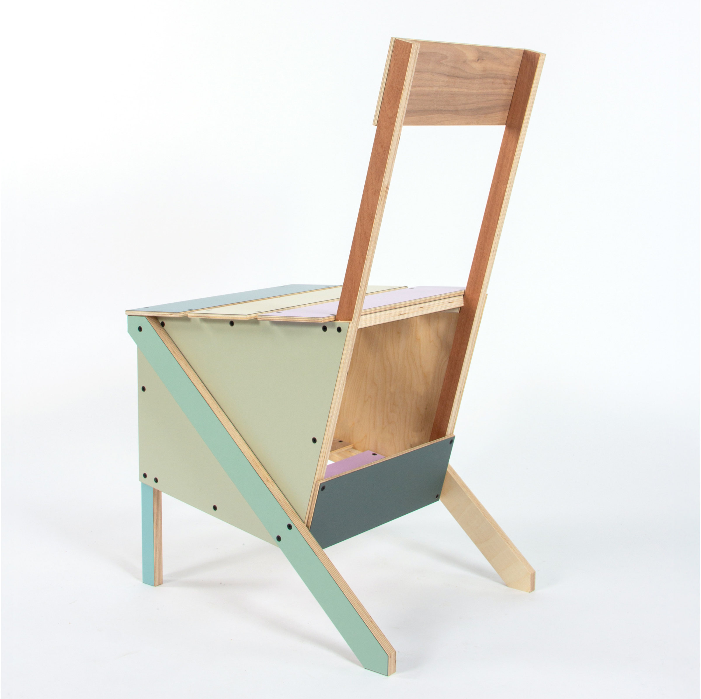
- 01
4° forward seat
The seat tips slightly forward to support an upright working posture.
- 02
Under-chair storage
A slatted shelf between the legs keeps a bag or books off the floor.
- 03
Colour from the offcuts
Each panel keeps the laminate colour of the offcut it was cut from.